Vibration Transmission and Isolation—Some Lesser-Known Facts
by Eric E. Ungar
Acentech, Inc., Cambridge, MA
Abstract
Vibration transmission and its reduction—that is, vibration isolation—play important roles in practice. It is pointed out that force transmissibility and motion transmissibility obey the same relation, not only for simple systems, but also for complex linear systems. The phenomena that cause mass, stiffness, and damping to affect transmissibility differently in different frequency domains are discussed. It is noted that vibration reductions provided by added masses (inertia bases) may be compromised by the practical limitations of the isolators supporting these masses. The magnitude of the vibrations transmitted to the support of a resiliently supported machine with a rotating imbalance is shown to be virtually independent of the machine’s rotational speed. The principle of reciprocity—the fact that the force-to-response ratio remains the same if the excitation and response measurement points of an elastic structure are interchanged—is delineated and discussed.
1. Introduction
Practitioners in the areas of noise and vibration control typically are familiar with the concepts of vibration isolation, particularly as characterized in terms of transmissibility. This article discusses several less well-known aspects of vibration transmission and isolation, which often are helpful in addressing real-world problems. Since the intent here is to provide practical insights, the discussions focus on simple configurations and rely on only a minimum of mathematics.
2. Force and Motion Transmissibilities
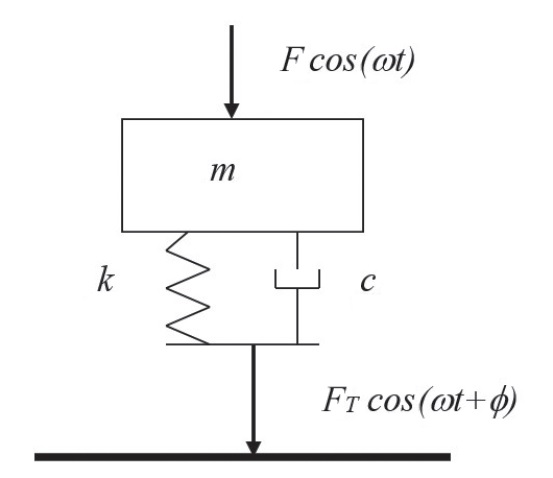
Almost every vibration textbook discusses vibration isolation in terms of a mass-spring-damper system represented by a diagram like that of figure 1 or figure 2. It shows a mass m supported on rigid support (represented by a heavy line) via a parallel arrangement of a spring with stiffness k and damper with viscous damping coefficient c. A sinusoidal force F cos \left( \omega t \right) at radian frequency ω is taken to act on the mass. The resulting motion of the mass compresses the spring and the damper, causing these elements to exert forces on the support, the sum of which makes up the total force F_{T}cos \left( \omega t+ \phi \right) transmitted to the support. The present discussion is concerned only with the magnitudes of the applied and transmitted forces: thus, the phase angle ϕ is not of interest here.
The ratio of the magnitude of the applied force to that of the transmitted force is called “force transmissibility”; it is defined as
T_{F}=F/F_{T} (1)
and may be shown to obey[I]
T_{F }=\sqrt[]{\frac{1+ \eta ^{2}}{ \left[ 1- \left( \frac{ \omega }{ \omega _{n}} \right) ^{2} \right] ^{2}+ \eta ^{2}}} (2)
where \omega_n = 2 \pi f_n = \sqrt[]{\frac{k}{m}} denotes the radian natural frequency of the system, with fn representing its cyclic natural frequency. The driving frequencies are similarly related and given by \omega = 2 \pi f .
The symbol η denotes the system’s loss factor. For idealized structural damping the loss factor is independent of frequency; for viscous damping—the situation covered in most textbooks—the η in the foregoing equation is replaced by c \frac {\omega}{k} = 2 \zeta \frac{\omega}{\omega_{n}} . (The second form of this relation is written in terms of \zeta , the ratio of the viscous damping coefficient c to the critical viscous damping coefficient c_{c}=2 \sqrt{km} .)
Note that for the case where the driving frequency is considerably greater than the natural frequency and damping is small the foregoing equation reduces to
T_{F} \approx \left( \frac{ \omega _{n}}{ \omega } \right) ^{2} (2a)
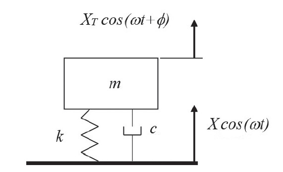
Now, instead of dealing with an applied force, consider the case where the support of a mass-spring-damper system vibrates with a displacement X cos \left( \omega t \right) , causing the mass to move with a displacement X_{T}cos \left( \omega t+ \phi \right) , as shown schematically in figure 2. The ratio of the magnitude of the base motion to that of the motion transmitted to the mass is called “motion transmissibility”; it is defined as
T_{V}=X/X_{T} (3)
Although the motion transmissibility here has been stated in terms of displacements, it may equally well be expressed in terms of velocity or acceleration.
It turns out that the expression for the motion transmissibility is the same as that for the force transmissibility, as given by equation (2). This equality of the force and motion transmissibilities, as discussed for the single-degree-of-freedom system of figures 1 and 2, holds not only for such simple systems, but also for any mathematically linear system, regardless of its number of degrees of freedom.[ii]
3. How a Mass, Spring, and Damper Contribute to Transmissibility
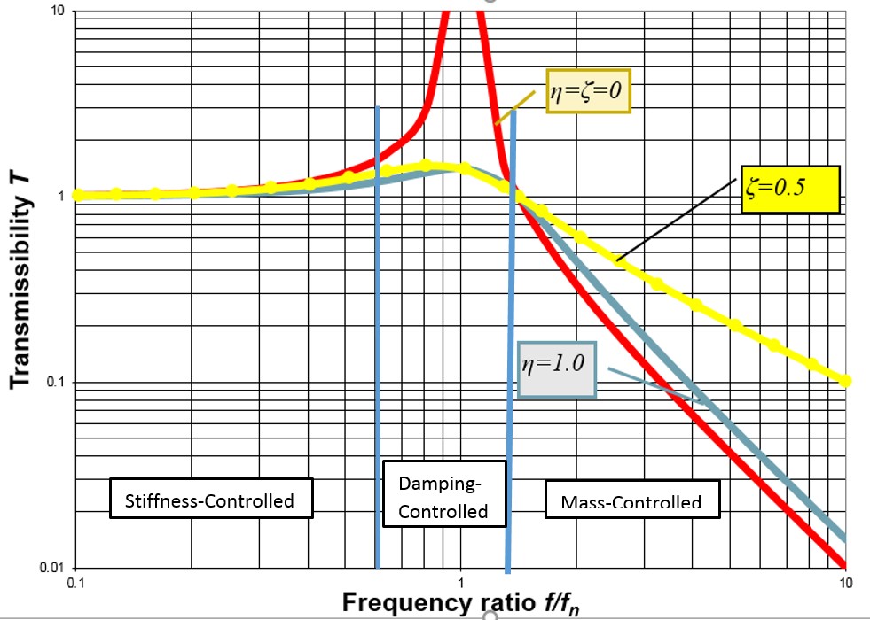
Figure 3 shows how transmissibility varies with frequency for several values of structural and viscous damping, as found from equation 2.
At frequencies well below the natural frequency the transmissibility may be noted to be only slightly greater than 1. Regarding force transmissibility (see fig. 1), this implies that the force FT that is transmitted to the foundation is essentially equal to the force F that is applied to the mass. Regarding motion transmissibility (see fig. 2), this implies that the displacement XT transmitted to the mass is essentially equal to the displacement X of the foundation. At these low frequencies, the inertia of the mass plays no significant role, so that an externally applied force applied to the mass is undiminished as it is transmitted to the spring, and this ideally mass-less spring transmits the force that is applied to it. Similarly, a motion of the foundation is transmitted undiminished to the mass, because the mass’s small inertia produces no appreciable deflection of the spring.
In contrast, at frequencies that are considerably higher than the system’s natural frequency the inertia of the mass plays a predominant role. Since the inertia effect increases with increasing speed of the mass’s motion, the motion-opposing effect of the mass increases with increasing frequency, thus resulting in lesser transmission of forces and displacements at higher frequencies.
At frequencies near the system’s natural frequency the spring-force and the mass’s inertia force in effect cancel each other, so that motion is controlled by damping. In this regime the energy that is supplied to the system per cycle by an external force or motion is equal to the energy dissipated by the system (i.e., by the damper) per cycle—and since greater damping limits the motion more severely, greater damping results in smaller transmissibility.
A damper that is connected between the foundation and the mass (in parallel with the spring) also transmits forces and motions between the two. A damper’s effect is small at low frequencies because the relative motions of its ends here are small, but its effect can be significant at high frequencies, particularly for viscous dampers that generate forces proportional to the velocity difference across them. Note that in figure 3 the red curve corresponds to zero damping, whereas the yellow curve corresponds to a viscous damper with the rather high damping ratio of 0.5. The yellow curve indicates that this viscous damper results in transmissibility values that are considerably greater than those for zero damping. The blue curve, which corresponds to the high structural loss factor value of 1.0, may be noted to deviate only slightly from the curve for zero damping, even though its transmissibility peak value (at essentially the natural frequency of the system) is equal to that of the yellow curve. This more benign behavior of a damper with structural damping is due to the damper’s force being proportional to its displacement, rather than to its velocity.
4. Effects of Inertia Bases
We often hear, “Add an inertia base to improve isolation.” Is this a good recommendation? Clearly, an added inertia base in effect increases the mass m and thus results in reducing the natural frequency f_{n}=2 \pi \sqrt[]{\frac{k}{m }} of a mass-spring system, with the consequence of reducing the transmissibility (improving the isolation) at excitation frequencies that are greater than the natural frequency (f > fn). The tacit assumption in the foregoing statement is that the spring stiffness remains unchanged. However, practical limitations on the carrying capacity of practical resilient elements (springs or pads) may lead to the use of more or stiffer elements, partially negating the natural frequency reduction and the isolation improvement due to the added inertia base.
As noted before, in the aforementioned high-frequency range (f > fn) the inertia force of the mass is much greater than the forces produced by the other elements of the system, so that the displacement amplitude of the mass in essence obeys X \approx F/m \omega ^{2} . Thus, addition of an inertia base (i.e., an increase in the mass) may be expected here to result in reduced excursion of the mass due to a given magnitude of applied force, unless the effective stiffness of the resilient elements is increased to such a great extent that the system’s natural frequency is no longer below the excitation frequency.
5. Isolation of Machine with Rotating Unbalance
Here is another often-heard statement: “Running a machine faster reduces transmitted vibrations.” Is this correct? It is true that higher rotation speeds result in increased f/fn and thus in reduced transmissibility if the machine’s isolation is sufficiently resilient. But that is not the whole story.
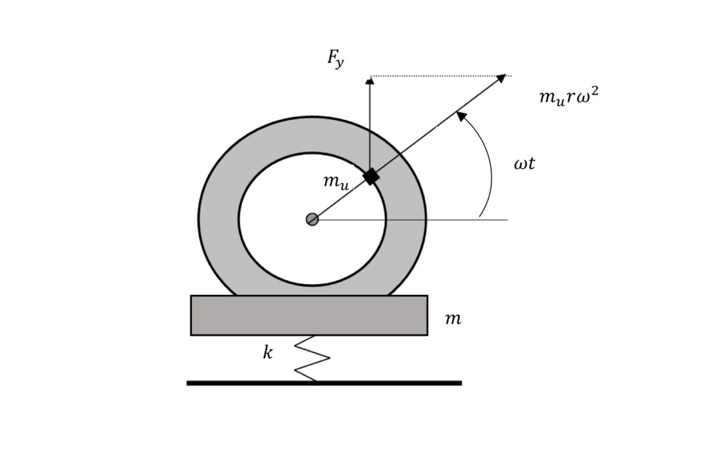
Consider an isolated machine of mass m with a rotor that has an unbalanced mass mu at a radius r, as sketched in figure 4. If the rotor spins at an angular velocity of \omega radians per second (=2\pi rpm/60) , this rotating unbalance produces a centrifugal force of magnitude m_{u} r \omega^{2} . The vertical component of this force then is F_{v} = m_{u} r \omega ^{2} sin(\omega t ) , and the magnitude of the vertical force transmitted to the support is given by F_{T}= m_{u}r \omega ^{2} T_{F} . With the force transmissibility from equation 2a (for \omega >> \omega _{n} and negligible damping) given by F_{T} \approx \left( \frac{ \omega_{n}}{\omega} \right) ^{2} the transmitted force becomes
F_{T} \approx m_{u}r \omega {n}^{2}=kr \frac{m_{u}}{m} (4)
Not only is this force independent of the rotational speed, but the displacement amplitude of the machine’s vibration produced by a rotating unbalance here is given by X=rm_{u}/m and also does not depend on the rotational speed. This relation indicates that if one knows the mass of the machine, one may deduce the magnitude of the imbalance rm_{u} of a machine mounted on resilient supports by measuring its vibration amplitude. This is the reason that the unbalance specifications of machines are often stated in terms of limits on the vibration amplitudes.
6. Reciprocity
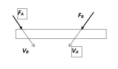
The principle of reciprocity, which applies to any mathematically linear system, in essence states that interchanging the force application and response observation points does not change the force-to-response ratio.
For a more precise description, let us refer to figure 5, in which the extended rectangle represents a general elastic structure.
Consider first that a force FA is applied to the structure at a given point in a given direction and that a resulting velocity VA is measured at another given point in another given direction. (The corresponding force and velocity symbols are shown in frames in the figure.) Then consider that a force FBis applied at the location where VA was measured and in the direction in which VA was measured and that there results the velocity VB at the point where the force FAwas applied and in the direction in which that force acted. (The symbols corresponding to this second case are shown without frames.) Then, according to the reciprocity principle, \frac{V_{A}}{F_{A}}=\frac{V_{B}}{F_{B}} .
Reciprocity often can be useful for analytical or experimental work, where one or the other of the variables may be difficult or cumbersome to measure or compute. For example, if one wants to determine the relation between a force acting in the interior of a machine structure (perhaps on an engine’s cylinder) and the vibrations it produces at a location on the exterior of that structure, it is rather difficult to apply a controlled force in the interior. It may be much easier to apply the force to the exterior and measure the interior vibrations (perhaps by means of a small accelerometer).
7. Concluding Remarks
A thorough understanding of the underlying background of the widely used vibration isolation relations should enable practitioners dealing with the reduction of vibration and the attendant noise to make better-informed judgments concerning the effects of changes in a system’s parameters. It should also facilitate appropriate consideration of the effects of inertia bases and of rotating unbalance. Consideration of the equality of motion and force transmissibilities may allow one in some situations to replace a given problem by one that can be addressed more readily. Similarly, application of the reciprocity principle may permit one in some practical cases to replace an experiment or analysis by a less burdensome alternative
[i] For example, see W. T. Thomson, Theory of Vibration with Applications (New York: Prentice-Hall, 1981).
[ii] Y. E. Lage, M. M. Neves, N. M. M. Maia, and D. Tcherniack, “Force Transmissibility versus Displacement Transmissibility,” Journal of Sound and Vibration 333 (2014): 5706–22.


