What Floor Vibration Will a Machine Produce When It Is Relocated?
By Eric E. Ungar, Acentech, Inc.
The Problem
In an often-encountered situation, a vibration-producing machine is to be moved from its present location to a new one without changing how the machine operates and one wants to predict the expected vibrations of the floor in the new location. If the floor structures are the same at the machine’s present and new locations, then the vibrations that the machine will produce in its new location will be the same as those it produces in its present location. But what if the floor structures at the two locations differ considerably?
Basic Considerations
The following discussion focuses on vibrations in the vertical direction, in which direction floors are most easily set into motion. However, the approach discussed below can be applied for any direction.
The vibration velocity V of the floor under a mounting foot of the machine depends on the vertical force F that the mounting foot exerts on the floor as V =F/Z, where Z represents the floor’s impedance at the point under consideration. (All symbols represent frequency-dependent magnitudes.) The vibration velocity of the floor at the machine’s future location then is related to that of the floor at its present location by
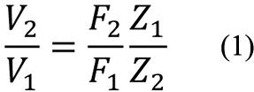
Subscript 1 refers to the machine’s initial location and subscript 2 to its future location. The foregoing expression permits one to take account of changing of the mounting foot’s force as the foot acts against a different floor impedance. If that force does not change when the machine is relocated, then the velocity V2 expected in the new location may be ascertained simply from the floor impedances Z1 and Z2 and the velocity V1, all of which can be measured relatively easily. (Note that the floor impedances need to be measured without the machine in place—or at least without the mounting foot under investigation in contact with the floor.)
Accounting for Change of the Vibratory Force
One may expect that in the general case the mounting foot will vibrate with a smaller amplitude and exert a greater force as it is made to act against structures that impede its motions to a greater extent. This change can be accounted for at least approximately by assuming a linear relation between the mounting foot’s force and its velocity—that is, taking the force/velocity relation as corresponding to a straight line (see figure).
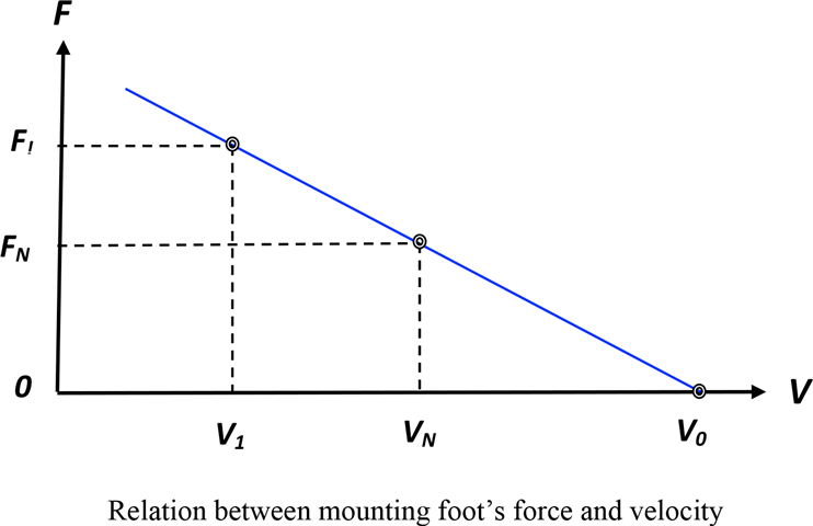
One readily established point on that line indicates the velocity V1measured at the machine’s foot in the machine’s initial location (with the machine in operation, of course) and the related force F1exerted by the foot. That force may be calculated from F1= Z1V1using the floor impedance Z1measured at the mounting foot location (without the mounting foot making contact with the floor). One may find a second point on the line by having the mounting foot act against a structure with a new measured or known “test impedance” ZN, measuring the corresponding new velocity VN, and determining the force FN = ZnVN. A test impedance may be realized, for example, by inserting a soft pad or mount with known properties between a relatively rigid floor and the mounting foot. (In a test configuration that is particularly convenient if it can be implemented practically, the foot is kept out of contact with any structure. In this case Fn = Zn = 0 andthe mounting foot’s velocity Vn can be measured relatively easily.)
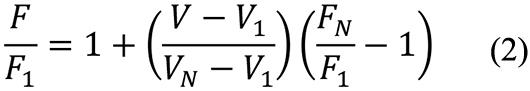
The force/velocity line indicates that the mounting foot’s force F is related to the foot’s velocity V as
If one applies this relation to the machine’s new location, identified by subscript 2, and combines the result with equation (1), one obtains
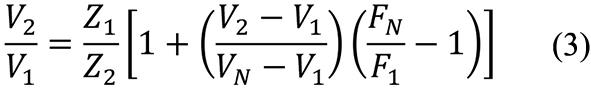
By solving this expression for V2/V1 one may determine the sought-for relation of the velocity V2 at the machine’s new location to the velocity V1 at its initial location:
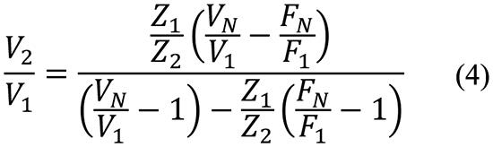
In the special case where the test impedance ZN = 0 (e.g., where the mounting foot was allowed to vibrate with no significant contact with any structure), FN = 0 and the foregoing equation reduces to
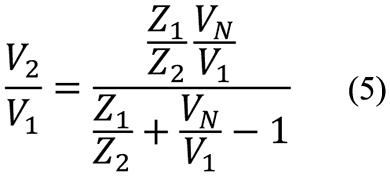
For the case where Z1 = Z2, the two foregoing equations yield V2= V1, as one would expect.
From equations (1) and (4) one may determine that
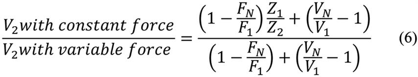
This relation indicates that assumption of a constant force results in overestimation or underestimation of the velocity the machine induces in the floor at the new location, depending on whether Z1 is greater than or smaller than Z2, respectively—in agreement with intuitive expectations.
Summary of Evaluation/Prediction Steps
- Measure the velocity V1 of the floor and mounting foot at machine’s initial location.
- Measure the impedance Z1 of the floor at machine’s initial location, without the machine (or mounting foot) in contact with the floor.
- If possible, measure the velocity V0 of the mounting foot as it makes no contact with the floor. Otherwise, measure the velocity VN that the machine produces on a support with known impedance ZN. (If a measurement is done with an isolator or pad that is much softer than the supporting floor, take ZN as the impedance of the isolator or pad.)
- Calculate the force FN = ZNVN. If the methodology of step (c) was used where the mounting foot was made to have no contact with a structure, take FN = ZN = 0.
- Measure the impedance Z2 of the floor at the machine’s planned location.
- Calculate the floor velocity V2 at the new location using equation (4). If FN = ZN = 0, use equation (5).</NL>
In the most general case this procedure would need to be carried out for each of a machine’s mounting feet. However, if all of a machine’s mounting feet behave similarly, this procedure needs to be carried out for only one mounting foot. All velocity and impedance measurements should be made over the frequency range of concern, but in cases where the machine produces significant vibrations only at a few frequencies, the measurements and calculations discussed here need only be carried out at these frequencies.
Some Background
Vibration sources with linear force/velocity characteristics are discussed in “High-Frequency Vibration Isolation,” by E. E. Ungar and C. W. Dietrich, Journal of Sound and Vibration, 1966, based in part on “The Evaluation of Mounts Isolating Nonrigid Machines from Nonrigid Foundations,” by A. O. Sykes, Shock and Vibration Instrumentation, ASME, 1956, and “Isolation of Vibrations,” by D. Muster and R. Plunkett, Noise Reduction, McGraw-Hill, 1960.