Sound insulation measurements according to ISO standards
By Jens Holger Rindel
1. Origin of ISO methods for sound insulation measurements
Sound insulation in buildings can basically be divided into two different kinds of measurements, the airborne sound insulation between two rooms and the impact sound transmission through a floor construction. While it is relatively straight forward to provide a loud sound source for the airborne sound insulation measurement, it is trickier how to generate a well-defined impact sound source. Forerunners of the tapping machine, which is used today for the impact sound measurements were developed around 1940 independently in Germanyi,ii and Americaiii. Measurements were made either as a broad-band level in Phon or in octave bands.
The first ISO recommendation for sound insulation measurements ISO R 140 appeared 1960.iv For measurements in a laboratory, any flanking transmission should be avoided. In all cases, measurement results should be adjusted to a reference absorption in the receiving room. The airborne sound insulation could be expressed either as the normalized level difference Dn (using 10 m2 as the reference absorption area), or as the sound reduction index R (Transmission Loss in American terminology) in dB:

where L1 and L2 are the average sound pressure levels in the source room and in the receiving room, respectively, S is the area of the test specimen, and A is the absorption area of the receiving room. While R was meant for laboratory measurements of building elements, the Dn was meant for field measurements where some flanking transmission is unavoidable. However, for comparison with laboratory results, the field measurements could also be expressed as an apparent sound reduction index R’.
The impact sound transmission is expressed as the normalized impact sound pressure level Ln in dB:
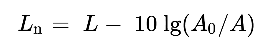
where L is the average sound pressure level produced by the tapping machine in the receiving room, A0 = 10 m2, and A is the absorption area of the receiving room.
Measurements should be made in octave bands (center frequencies from 125 Hz to 4000 Hz), or in 1/3 octave bands (center frequencies from 100 Hz to 3200 Hz). Measurement results should be reported as function of frequency in tables or graphs.
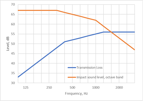
International methods for deriving single-number values from the measurement results were established 1968 in the ISO recommendation ISO R 717.v The principle is that a frequency-dependent weighting curve is compared with the measured curve of sound insulation, adjusted up and down to fulfill some rules for a fit, and in addition the unfavorable deviation at any frequency should not exceed 8 dB. The single-number index was the value of the shifted reference curve at 500 Hz, see Figure 1. The results were the airborne sound insulation index Ia and the impact sound index Ii. The measurements should preferably be made in 1/3 octave bands. However, impact sound levels could either be measured in octave bands, or the 1/3 octave band levels should be corrected to octave band levels by adding 5 dB.
It is remarkable, that ISO R 717 refers specifically to field measurements, but the normalized level difference Dn is not mentioned. The measures to be evaluated are the apparent sound reduction index R’ and the normalized impact sound pressure level. The proposal was very similar to the German practice at the time, but several countries voted against the proposal, probably because they were using the normalized level difference in the building codes. However, ISO R 717 was accepted by the majority as an international standard.
2. Current ISO standards on sound insulation
2.1 Measurements
The measurement methods are basically the same as in the first recommendations from 1960, although some details have been further developed. The current measurement methods on sound insulation are divided into laboratory measurements on building elements and performance measurements in the field. In addition to the impact sound insulation of floor constructions and the airborne sound insulation of partition walls or floors, there are methods for the sound insulation of windows and facades. An overview of the relevant current ISO and ASTM standards is presented in Table 1.
Table 1. International (ISO) and American (ASTM) standards for measurement of sound insulation. (Adapted from Rindel 2018, Table 12.1). vi
| Building elements measured in a laboratory | Performance measurements in the field | |
| Airborne sound insulation, walls and floors | ISO 10140-2 (2021) ASTM E90-23 | ISO 16283-1 (2014) ASTM E336-25 |
| Airborne sound insulation, windows and façades | ISO 10140-2 (2021) ASTM E90-23 | ISO 16283-3 (2016) ASTM E966-18 |
| Impact sound insulation | ISO 10140-3 (2021) ASTM E492-25 | ISO 16283-2 (2020) ASTM E1007-25 |
The frequency range of measurements in a laboratory is in 1/3 octave bands from 100 Hz to 5000 Hz, optionally down to 50 Hz. Field measurements are made from 100 Hz to 3150 Hz, optionally down to 50 Hz and including also 4000 Hz and 5000 Hz.
2.2 Single number values
Single-number values for sound insulation are defined in ISO 717. The current version of ISO 717 from 2020 is divided into two parts for airborne and impact sound insulation, respectively. The weighting curves in Figure 1 are kept, except that the curve for impact sound is shifted down by 5 dB when applied to 1/3 octave band measurements. The former 8 dB rule for maximum unfavorable deviation is no longer in the standards.
For laboratory measurements of airborne sound insulation, the main result is the weighted sound reduction index Rw, which is approximately equal to the sound transmission class STC as defined in ASTM E413-16. The weighting curve for STC is the same as in ISO, except that the frequency range is from 125 Hz to 4000 Hz and the 8 dB rule is applied.
The main result of a laboratory measurement of the impact sound transmission is the weighted impact sound pressure level Ln,w. This can be compared to the impact sound insulation class IIC as defined in ASTM E989-06. The frequency range and the weighting curve is the same as in ISO, but the 8 dB rule is applied. The IIC number is approximately equal to 110 dB – Ln,w. Thus, a floor with good impact sound insulation is represented by a low value of Ln,w but a high value of IIC.
2.3 Normalized or standardized measures
When it comes to field measurements of sound insulation, the ISO standards open up for two options: Either the normalized results using a reference absorption area as in laboratory measurements, or the standardized results using an adjustment to a reference reverberation time of 0.5 s in the receiving room. The airborne sound insulation can be expressed either as the weighted apparent sound reduction index R’w or as the weighted standardized level difference DnT,w. Similarly, for impact sound measured in a building, the result can be expressed either as the weighted normalized impact sound pressure level L’n,w or as the weighted standardized impact sound pressure level L’nT,w. As could be expected, the result is that some countries are using the normalized measures in their building codes, while other countries are using the standardized measures.
2.4 Spectrum adaptation terms
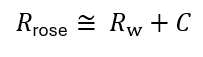
Since the 1996 edition of ISO 717, there has been a set of spectrum adaptation terms that apply to the weighted single-number results. For the airborne sound insulation this can be seen as a compromise between German and French methods. While the method with the weighting curve has a German origin, the traditional French method was to calculate the A-weighted level difference assuming a certain spectrum of the sound in the source room. These measures were called Rrose and Rroute, referring to a pink noise spectrum or a road traffic noise spectrum, respectively. With the spectrum adaptation terms C and Ctr defined in ISO 717, it was possible to make the following relationships:
Rrose≅ Rw+C
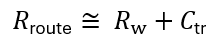
and
Rroute≅ Rw+Ctr
The relationships can be made exact if the spectrum adaptation terms include the frequencies up to 5000 Hz. Then the spectrum adaptation term for Rrose is written C100-5000.
The introduction of spectrum adaptation terms opened up for extension of the frequency range applied in the evaluation of measured sound insulation. Thus, it became a way to include frequencies below 100 Hz without changing the weighting curves. For airborne sound insulation, the spectrum adaptation term C50-3150 means that the 1/3 octave bands 50 Hz, 63 Hz, and 80 Hz are included in the evaluation using a pink noise spectrum. The importance of including the low frequencies in airborne sound insulation between dwellings has been documented in several research projects.vii
A spectrum adaptation term has also been defined for impact sound insulation, denoted CI. It normally covers the frequency range 100 Hz to 2500 Hz and is so defined, that it is close to zero for massive floors with an effective floor covering, while it becomes positive for timber joist floors with domination low frequency transmission. With extended frequency range down to 50 Hz the impact spectrum adaptation term is CI,50-2500. When added to the weighted impact sound pressure level, the result has been shown to correlate well with subjective evaluation of floor constructions, lightweight as well as heavyweight with or without a floating floor on top.viii The referred investigation also showed that the weighted impact sound pressure level without the CI,50-2500 adaptation term had no correlation at all with the subjective evaluation. This emphasizes the importance of including the low frequencies in measures for impact sound.
With all possible combinations of normalized or standardized measures and possible extended frequency ranges, see Table 2, the ISO methods for evaluation of sound insulation has become like a catalogue of options, far from harmonization.ix
Table 2. Some possible measures for sound insulation in dwellings according to ISO 717 part 1 and 2.
| Frequency range 100 Hz – 3150 Hz | Extended frequency range | |
| Normalized airborne sound insulation | R’w or R’w + C | R’w + C50-3150 |
| Standardized airborne sound insulation | DnT,w or DnT,w + C | DnT,w + C50-3150 |
| Normalized impact sound insulation | L’n,w or L’n,w + CI | L’n,w + CI,50-2500 |
| Standardized impact sound insulation | L’nT,w or L’nT,w + CI | L’nT,w + CI,50-2500 |
2.5 Method for low frequencies in small volumes
The extended frequency range below 100 Hz raises an issue about how to measure a meaningful average sound pressure level in small volumes, because the modal density is low and the sound field is far from being a diffuse sound field at these low frequencies. In volumes smaller than 25 m3 a special low-frequency procedure is prescribed in ISO 16283-1 for the 50 Hz, 63 Hz, and 80 Hz 1/3 octave bands. In addition to measurements in the central zone of the room, the sound pressure level is measured in a corner of the room. The energy-averaged sound pressure level is calculated with 1/3 weighting factor on the corner result and 2/3 weighting factor on the central result.
The measurement of reverberation time at these low frequencies may be difficult or even impossible. Therefore, the low-frequency procedure prescribes that the reverberation time at the 63 Hz octave band is measured and applied to the 1/3 octave bands 50 Hz, 63 Hz, and 80 Hz.
2.6 Windows and facades
Field measurements of the sound insulation of windows and facades are described in ISO 16283-3. There are two different kinds of measurement, the global method that evaluates the entire façade, and the element method that evaluates a particular building element (a window).
The sound source can be either the traffic noise at the location or a loudspeaker in a prescribed outdoor position. For the global method, the traffic noise source is preferred. The outdoor sound pressure level L1,2m is measured 2 m in front of the façade, and the indoor sound pressure level L2 is measured as a spatial average using a moving microphone or five fixed microphones. Measurements are made in 1/3 octave bands and the result can be the standardized level difference:
where T is the reverberation time and T0 = 0.5 s.
Measurements after the element method should preferably be made with a loudspeaker that emit sound towards the element at an angle of 45°. The outdoor sound pressure level L1,s is measured at the surface of the test element (window), while the indoor sound pressure level L2 is measured as usual. The results can be the apparent sound reduction index at 45°:

where S is the area of the test element and A is the absorption area of the receiving room.
Single-number results can be derived using the spectrum adaptation term for traffic noise Ctr with normal frequency range or extended frequency range.
3. Summary
This article is a brief overview of the ISO methods for measuring and evaluating sound insulation in a laboratory and in the field. Several more special kinds of measurements exist but have not been mentioned here. That includes measurement of flanking transmission through junctions, walls, suspended ceilings, etc.
About the author

Jens Holger Rindel has more than 50 years of experience in architectural acoustics and has been professor in acoustics at the Technical University of Denmark until 2007. He is the founder of Odeon A/S developing room acoustics software. He is a Fellow of the Institute of Acoustics and of the Acoustical Society of America, and Honorary Member of the acoustical societies of Denmark and Norway. He has published textbooks on building acoustics and on architectural and environmental acoustics. He was chairman of the Technical Committee for Building and Room Acoustics of European Acoustics Association 2001-2007. For more than 35 years he has been involved in international standardization and has been convenor of several ISO working groups. In 2000-2006 he was the leader of EU-projects within cultural heritage studying the acoustics of ancient worship spaces and Roman theatres.