Floating floor design in 2026
By Wilson Byrick, VP Engineering Services, Pliteq Inc.
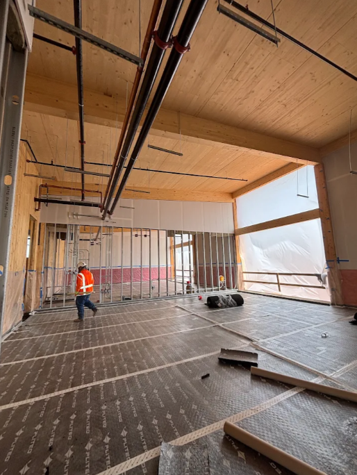
Floated floors on discrete isolators, such as rubber mounts, foam pucks, or springs, are common in sound and vibration isolation design. Whether the floating floor is being used for isolation of airborne sound (performing arts), vibration (mechanical and lab equipment) or impacts (fitness and sports) there a few aspects of the design that should be considered.
The traditional method of determining the natural frequency of a spring element is to consider the deflection under load and use Hooke’s law. However, in a compressible non-isovolumic elastomer this relationship of load and natural frequency is non-linear, and the material properties must be measured.
If the floated mass layer is installed without sufficient venting, the entrapped air between the isolators will introduce its own stiffness, contributing to the overall natural frequency of the system. If this stiffness is neglected in design, the natural frequency of the system can be significantly higher than predicted, potentially leading to unexpected field performance. This is a critical issue when floated slabs are employed to isolate specific driving frequencies.
This problem is further complicated when a floated floor is not slab-on-grade. When a floated slab is supported by a suspended structural slab, the system no longer behaves as a single-degree-of-freedom (SDOF) system but rather as a two-degree-of-freedom (2DOF) system, due to the dynamic nature of the supporting floor. If the stiffness of the suspended structural slab is not accounted for in the natural frequency analysis, the overall system will not perform as predicted.
Air stiffness and venting radius
When both discrete isolators and an unvented air cavity are present, the air and isolators will act as ‘springs in parallel’, meaning their stiffnesses must be combined to calculate the overall natural frequency (𝑓n) of the floated floor. This evaluates the single-degree-of-freedom (SDOF) frequency, which can be used in slab-on-grade applications where the structural slab can be considered ‘infinitely rigid’.
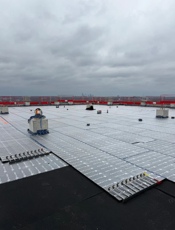
In 1975, Eric Ungar derived the venting radius criteria based on the thermodynamic behaviour of air. This establishes requirements for the venting area necessary to avoid air stiffness contributions in a floated floor. He states that: “A floated slab may be considered as adequately vented if vents of area 2πRL/h for each πR2L floor area are provided. “ To calculate this, using 2ℎ/𝑅L as a percentage of the total floor area will determine the vented area required. What this does not consider, is ‘partial venting’. In practice, an installed floating floor likely has some vented area, but perhaps not enough to consider the floor fully vented. This is due to architectural or structural constraints. For example, a rooftop swimming pool or basketball court with discrete isolators would need to be vented through the structural slab, but this would increase any airborne noise transmission through the assembly into the space below.
For the 2025 ICA/ASA conference in New Orleans, we published research into partial venting. A small-scale laboratory mock-up was built using a sealed box and a GenieMatTM FF70LDM panel – a 590 mm x 590 mm panel with 9 pre-adhered isolators and mineral wool insulation. The isolators are 50 mm thick, and the mineral wool is 35 mm thick. The panel was placed in a box to allow a 6.4 mm air gap along the perimeter. A 20 mm concrete panel on top was added to increase the loading and test a more representative load range. This assembly assumed complete venting, as there was sufficient perimeter gap for air to flow. It was placed onto a test frame where a frequency sweep at discrete loading intervals was performed.
To simulate the unvented situation, a plastic sheet was used to cover the top of the box. The sheet was pulled taught and taped to seal the box, ensuring that there were no gaps for air leakage. The same frequency sweep was performed with the unvented assembly. Holes in the plastic sheet along the perimeter were punctured, of 5 mm diameter each, to simulate partial venting. With 2, 4, 8, and 16 vents, a frequency sweep was performed again for each of these conditions at the same loads. This data is shown in the figure below.

By using this data, we can better predict the effect of partially vented floating floors based on the vented floor area as a percent of total area. Further research showed significantly less change in overall system natural frequency when continuous elastomeric floating floor elements were used.
Considering the second degree of freedom
When floating floors are located on elevated structural slab the dynamic response of the structural slab needs to be considered. The concrete slab needs to be considered as both a mass and a spring and not infinitely more rigid than the single degree of freedom floating floor above it. When the structural slab is considered in this way, the single degree of freedom natural frequency shifts to the left and a new second harmonic appears to the right of the structural slab natural frequency. The amplitude and width of the second harmonic is difficult to predict and varies significantly with the venting condition.
In a paper presented at Inter-Noise in 2019, Zhuang Li from McNeese State University discusses how the use of SDOF models is insufficient for evaluating the natural frequency of floating floor systems on suspended structural slabs. Where a suspended structural slab introduces its own stiffness contribution, a two-degree-of-freedom (2DOF) model is more suitable. Practical examples include rooftop mechanical rooms, rooftop swimming pools, elevator shaft mechanical rooms, and gymnasium floors that incorporate floating slabs. Although 2DOF models themselves are well established in vibration theory, it was Li who derived the theoretical formula for damped 2DOF vibration transmissibility.
Using this model and laboratory measured material properties Pliteq engineers developed a calculator tool which can output two degree of freedom transmissibility data when inputs are provided. Engineers have access to this tool on Echo OneTM. Input variables include the floating floor load, the selected isolation material, load of the structural floor and the natural frequency of the structural floor.
Predictive modelling vs. field measurements
In May 2025, field tested measurements were collected by engineers from Brown Strachan Associates in Vancouver, Canada. The application was a 70 m2 gym being installed on the 2nd floor of an existing mixed-use building. Vibration measurements were taken on the top of the slab before and after the installation of both the isolators and the 100 mm concrete topping. Two impact locations and 11 accelerometer locations were chosen. To excite the structure but not cause damage to the structure, a 24 kg weight was dropped on an 8 mm rubber sheet. The concrete topping was installed over the perimeter isolation to the walls, so the air within the system was sealed.
The isolator natural frequency based on simple SDOF analysis and loading was 5.83Hz. When air stiffness and the structural stiffness were included in a full system 2DOF analysis, Echo OneTM predicted a low natural frequency of 11.8Hz and high natural frequency of 25.7Hz. The prediction and field testing matched as a resonance at 26Hz was measured onsite. It is imperative that manufacturers and designers consider a more detailed model in the design of floating floors if they want to accurately predict in situ performance.
For more information on the literature or research discussed in the above article please contact Wil Byrick at wbyrick@pliteq.com.