Monumental staircase vibration: finite element analysis and post-construction testing
By Roman Wowk – Principal, Papadimos Group
Monumental staircases have become a focal point in modern architecture. These three-dimensional sculptures, often associated with an atrium, improve occupant flow between floors and entice people to skip the elevator. Some of the larger or more elaborate staircases even function as gathering zones for casual collaboration, all-hands meetings or to provide spillover space during crowded events.
Presented below is an example of a simple but common monumental staircase configuration consisting of a linear span across an atrium with an intermediate landing. Finite element analysis (FEA) was used to evaluate vertical vibration under walking excitation and develop upgrades for vibration control. After construction was complete, vibration testing was done to verify that the design objectives were achieved and to check the accuracy of the FEA vibration predictions.
Vibration Criteria
ISO Standard 2631-2 defines a base curve for human perception of vertical vibration in terms of Root Mean Square (RMS) acceleration, with values of approximately 0.05% gravity in the 4 through 8 Hz ⅓-octave bands and gradually increasing values outside those bands. That standard also defines multiplying factors to this curve of 4 to 128 for office environments depending on whether the vibration is continuous or transient in nature. Design Guide 11 by the American Institute of Steel Construction specifically addresses vibration due to footfall excitation and recommends a multiplier of 10 to the ISO base curve for offices and a multiplier of 30 for indoor footbridges. The higher limit for indoor footbridges takes into account that people are more tolerant of vibration when moving rather than sitting or standing still.
For the design of this staircase, the office criterion was targeted as a goal while the indoor footbridge criterion was set as an upper limit. The reasoning behind this approach was that people may stop at the intermediate landing for short periods but will otherwise be in motion most of the time. Other larger and more elaborate staircases where people may linger for long periods of time or gather to watch presentations may require more stringent design criteria.
Finite Element Analysis
A finite element model was developed using SAP2000 that included the stair stringers, treads and one structural bay on the top and bottom of the staircase (see Fig. 2). In addition to the basic material properties of steel and concrete, the following assumptions were made regarding the initial structural design:
- Connections between stringer sections: translational and rotational degrees of freedom connected (“full-moment” connection).
- Connections between top of stringers and base structure: translational degrees of freedom connected but rotational degrees of freedom released (“pinned” connection). Since the actual condition would be somewhat fixed and not truly free rotationally, this is a conservative assumption.
- Connections between bottom of stringers and base structure: translational degrees of freedom connected vertically and laterally perpendicular to stringers but all other degrees of freedom released (“slip” connection) between bottom of stringers and base structure.
- Live loads: up to 1,000 pounds of live load distributed across the stair span (in addition to the self-weight of the structure) was initially considered. However, since initial tests showed that this did not significantly reduce the frequency of the dominant mode and only improved vibration, zero load was ultimately used as a worst-case assumption.
Time history analysis was then done by appropriately meshing the model and solving for an adequate number of modes to capture vibration up to about 50 Hz with a vertical force function of a walker at the middle of the intermediate landing. This location is an obvious choice for where vibration would be highest, which was confirmed by reviewing mode shapes and frequencies prior to running time history analysis.
The forcing function used is based on typical brisk walking speeds in the range of 90 to 100 paces/min. However, some margin was also applied to account for real-world conditions such as higher forces when descending stairs rather than walking on a level surface, multiple walkers in-step and potentially higher walking speeds.
Predicted vibration for the base design as described above was up to a factor of five above the desired range (see Fig. 3) and exhibited a vertical dominant mode (i.e. “natural frequency”) at 6 Hz. Rather than upgrading the stair stringers, which would increase steel quantities, a full-moment rather than pinned connection at the top of the stringers was considered. This relatively easy design change, which takes advantage of the stiffness of the base structure, increased the natural frequency to 7.3 Hz and reduced predicted vibration to within acceptable design limits (see Fig. 3).
Vibration Testing
After the staircase was completed, vibration was measured by placing an accelerometer at the middle of the intermediate landing (see Fig. 4) while ambient conditions and a variety of footfall inputs were tested. Measured vibration agreed closely with the predictions in terms of both spectral shape and amplitude, and confirmed that the design goals were met (see Fig. 5). Running was the only tested condition that produced vibration above the upper design limit (i.e. for indoor footbridges); however, this is not a regular use case and the exceedance was marginal. Typical walking produced vibration levels close to the lower design limit (i.e. for offices) and a “quick” descent produced vibration levels about halfway between the office and indoor footbridge limit.
Conclusions
This case study illustrates the power of Finite Element Analysis (FEA) in streamlining the design process and adding confidence to design decisions. With proper validation based on testing from previous projects, it can be successfully used to tackle complex problems, develop design options and visually communicate results and aid in the decision making process. Yet it can also be deceivingly wrong. Caution must be exercised to catch and eliminate errors in input assumptions, bugs in models or over-simplifications that completely mask a problematic condition. This is best done by continuously questioning design assumptions and conventional thinking, breaking down problems into their most basic elements and by checking predictions against real-world data.
Prior to relying on FEA for critical design decisions, measured data and test models of similar structures should be used to understand the degree of uncertainty in the predictions and to understand which input assumptions most contribute to errors. The lessons learned and refinements gained from that process can then inform design decisions that offer significant cost benefits and/or performance commitments. On this particular project, the sizing of the stair stringers was minimized and the architectural design intent was preserved through confidence in properly-validated FEA predictions. Similar cost savings and architectural innovation are possible on a wide array of projects that face potential issues from footfall excitation and other vibration sources.
Acknowledgements
Thank you to the entire Papadimos Group team for supporting this article and building our vibration practice by asking tough questions, running towards challenges, “earning the data” with difficult field measurement assignments, and bringing unique perspectives to each project.

Figure 1. Photo of staircase.
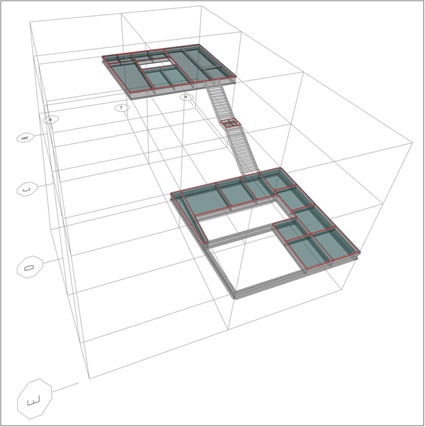
Figure 2. Screenshot of finite element analysis model (using SAP2000).
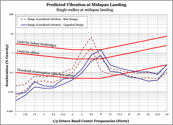
Figure 3. Vibration predictions for initial vs. final design

Figure 4. Vibration testing with accelerometer at intermediate landing.
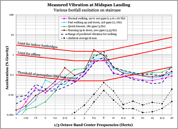
Figure 5. Measured vs. predicted vibration for final design