Establishing an Industry Benchmark: Mercury Marine Builds Innovative World-Class Testing Facility
By Peter G. Lynde, PE
On December 6, 2018, Mercury Marine unveiled their new Noise, Vibration, and Harshness (NVH) Technical Center during a grand opening event held at their Product Development & Engineering (PD&E) Center in Fond du Lac, Wisconsin. This article recounts the journey taken by the owner, architect, engineers, contractors, and suppliers who, together, turned their vision into reality.
The Mercury Marine Vision
Mercury Marine has been at the forefront in NVH testing and development of marine products for decades. They consistently lead the industry in the production of outboard and sterndrive motors possessing world-class NVH attributes. In 2000, they opened their Plant 12 Sound Lab at their Wisconsin PD&E Center—a hemi-anechoic test room complete with a water tank designed to test outboard motors up to 250HP. This facility served Mercury Marine well for over a decade, but its use became limited due to the relentless evolution of product technology and motor horsepower. Mercury Marine recognized that a new facility was needed to test their future product mix and improve the NVH quality of their prop to helm marine propulsion solutions.
To continue as a leader in the marine segment in NVH attributes, additional test capacity was needed to meet and exceed product development goals. Two primary objectives established at program onset set the stage for the new facility:
- The Technical Center would support all NVH development activities for Mercury Marine and support NVH development across the entire Brunswick product line.
- The Technical Center would be located at the Mercury Marine PD&E Center to encourage and facilitate interaction and collaboration with their product development and engineering staff.
Though simply stated, meeting these two objectives would prove highly significant in the ultimate configuration of the facility.
Facility Configuration
In addition to satisfying the two primary program objectives, Mercury Marine identified several requirements deemed essential in the new facility.
Overall Facility Layout
The placement of the facility had to maintain proximity to Mercury PD&E, while allowing the facility to be separate to achieve aggressive performance targets. The facility must also allow free movement of Mercury and non-Mercury personnel through the public area of the facility, while maintaining compartmentalized control of the nonpublic spaces to ensure project confidentiality. In addition, it must be a low vibration environment designed to mitigate vibrations transmitted into the facility so that noise and vibration testing and sound level measurements would be highly accurate.
Test Facilities
Two highly flexible fully capable test chambers would be designed specifically for testing marine products. However, these chambers must also be configurable into standard hemi-anechoic spaces to test a wide array of products. These chambers must maintain a high level of flexibility and capability, not just for now but also for the future. There must be a low noise floor (low SPL) in the test chambers assuring that Mercury Marine is able to continue to develop products with “world-class” NVH attributes. The chambers had to allow for testing of higher HP engines, as industry trends have made clear the need to accommodate larger engines.
Support Facilities
It was important to consolidate NVH testing and support areas into one facility to optimize team efficiency. A jury evaluation/listening room was needed to perform jury evaluations of the sounds of Mercury products. The room had to be quiet enough to allow for undisturbed evaluation, but not so quiet that it created an unnerving environment for participants. Guest office and breakout rooms were required to provide temporary touchdown spaces for customers and visitors in the public area of the building. An engineering technician area was necessary to provide Mercury engineering technicians with the ideal place to perform their duties, while remaining efficient and organized. A modal MOI/CG test area was important to provide a space for performing modal analysis of products. The space must include a robust support structure to suspend engines and measure their Center of Gravity (CG) and Moment of Inertia (MOI). Lastly, a large indoor vessel instrumentation bay was needed to provide an indoor area for vessels up to 45 feet in length to accommodate development activities.
NVH Staff Office Space
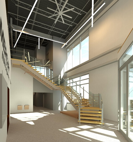
The office space design incorporates floor-to-ceiling windows, infusing a combination of home base workstations and an open collaborative area with natural light. Upper cabinets and high lockers were omitted from the design plan to reduce visual mass and to maintain an open feeling. Stand-up workstations are located throughout the personal and common areas to encourage working while standing. Nontraditional workspaces are included to help further drive collaboration and innovation. LED lights are used throughout the facility to reduce energy consumption and improve work area comfort. In-floor heating is located on the outer walls of the first-floor lobby and test spaces to increase occupant comfort.
Engineering and Design
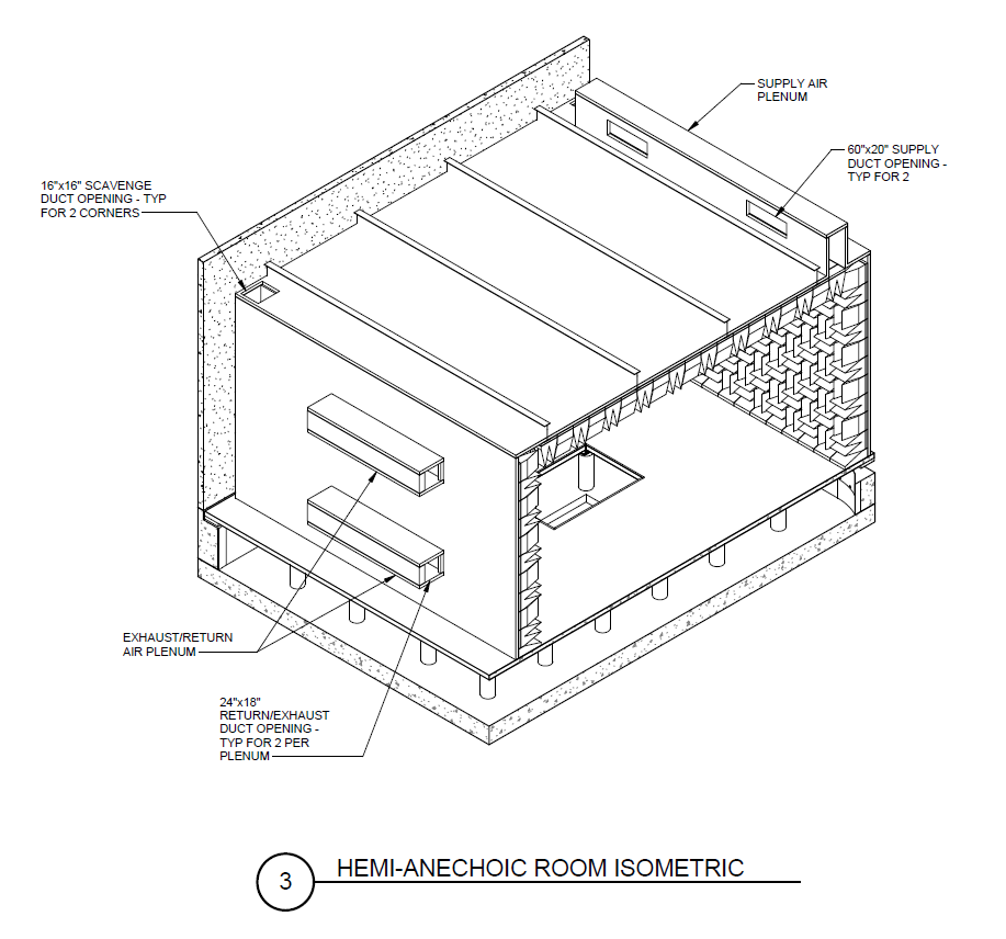
Extensive use of 3-D modeling was employed during the design and engineering stages to help visualize the many complex interrelationships of the facility. Kahn utilized Revit and Revit MEP modeling software to accurately coordinate and integrate building systems and easily create isometric views (fig. 1). Visualization tools such as Revit Live and Google cardboard were used to create “fly-throughs” and virtual reality simulations of the building, allowing Mercury to fully understand the interior and exterior images the building would present (fig. 2).
Vibration Mitigation
An early task in the engineering of any new facility is the geotechnical investigation. This task was expanded to include ambient ground vibration measurements due to the sensitive noise and vibration testing planned for the facility. In order to ensure low background noise levels within the test facility, isolation of the test chambers was of paramount importance to mitigate structure-borne vibration transfer into the hemi-anechoic test chambers. Testing confirmed suspicions that undesirable low-frequency vibration levels were evident in the soil, and these were attributed to multiple sources, ranging from heavy vehicle traffic on the nearby Highway 41 to snowplow activity in campus parking lots. It was clear that engineered systems would be required to block these unwanted vibration levels from disrupting NVH testing in the new facility.
Marine product testing must replicate the open water environment to best simulate real world NVH characteristics. Each NVH test room is placed over a basement water reservoir. Though independent from each other, the basements share a common concrete mat foundation, which also serves as the floor of the reservoir. The mat foundation is 24-inch-thick steel-reinforced concrete bearing on compacted native soils. The mat foundation supports poured concrete walls and piers that, in turn, bear the load of the test room concrete slab. The perimeter foundation walls average 36 inches thick to resist the lateral forces associated with water on one side and earth on the other, as well as the unique geometry required for the vibration isolation systems. The high mass afforded by the foundation mat and walls mitigates the transmission of unwanted ground-borne vibration into the structure. To further attenuate unwanted ground-borne vibration, a three-foot band of sand material, in lieu of the native clay soils, was used for back-fill around the entire depth of the perimeter foundation walls.
Vibration Isolation
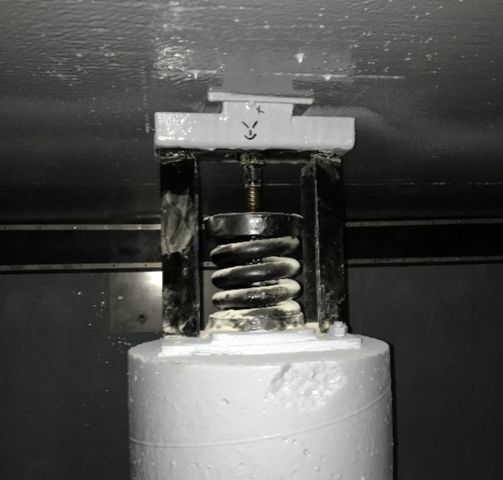
Hemi-anechoic test facilities are nothing new within the NVH testing community; however, supporting test rooms on a steel coil vibration isolation system above a 66,000 gallon water reservoir was viewed as a one-of-a-kind installation (fig. 3). Driven by the presence of undesirable ambient ground vibration, isolation of the acoustic test chamber was deemed essential. Once value engineering analyses concluded coiled steel springs to be the best choice for the isolation system, the challenge became how to integrate these springs into the test facility. Test room floors are 6-inch-thick steel-reinforced concrete slabs designed for added stiffness to mitigate the potential for floor resonance. Vibration isolating mounts are placed between the foundation walls/piers and the underside of the test room floor and serve to isolate the test room floor and acoustic room structure from any remaining unwanted ground-borne vibration. The acoustic panel test chamber and its steel structural frame are supported on the perimeter of the floor slab, where the slab transfers its dead and live loads through a total of 42 steel coil isolation mounts. Mount loadings vary considerably and range from 2 kips to nearly 12 kips. Steel spring isolating elements afford 90 percent isolation efficiency from disturbing frequencies of 8 Hz and higher.
Engineered Water Reservoir
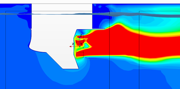
Testing of marine products, specifically outboard motors, requires a water reservoir to receive the thrust from engine props, but just a simple water tank is not enough. Replication of the flow characteristics realized in open water conditions was critical to accurately simulate the real-world environment. To achieve this state, Mercury engineers used computational fluid dynamics (CFD) analysis to optimize the depth and shape of the reservoir to mitigate unwanted turbulence and wake formation (fig. 4). The CFD analysis aided in confirming placement of floor support piers, ideal radius of reservoir corners, and configuration of underwater baffle plates. The CFD analysis also served as a value engineering tool, allowing initial conservative estimates of reservoir depth to be reduced substantially, lowering excavation and foundation costs. At full operating depth, the reservoir capacity is approximately 66,000 gallons.
Acoustic Isolation Systems
The exterior walls surrounding the test rooms prevent unwanted external sound sources from reaching the indoor test environment. Exterior noise events could easily produce ambient noise levels in excess of 80 dBA. These noise events could include construction activity; truck noise from the nearby Highway 41, Military Road, the service access road, and truck docks; as well as small aircraft or helicopter flyovers. These events are inherently unpredictable and unavoidable even by careful test scheduling.
With test room noise floor targets nearing NC-10, a minimum sound transmission class of STC-56 was necessary to afford effective reduction of unwanted sound from surrounding site activities. Research into precast concrete products found panels offering sound transmission class ratings as high as STC-61. With precast concrete a preferred choice, and part of the campus architectural vocabulary, the decision was made to construct the exterior perimeter walls with precast insulated concrete panels.
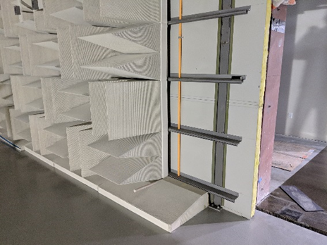
Room-within-a-room configuration was chosen to ensure maintenance of targeted background sound levels. With ground-borne vibration a concern, and test room isolation essential, the inner test room was best constructed of metal acoustic wall panels to significantly reduce the loading on vibration isolation mounts. Mercury selected Eckel Acoustics to supply the acoustic test rooms and their perforated metal anechoic wedge system to line the interior. Eckel furnished and erected the test room as a complete assembly with structure, panels, wedges, and doors, guaranteeing specified acoustic performance parameters were met.
Test Room Sizing
Originally conceived as a test facility exclusively for marine products, Mercury NVH Engineers advised the project team that Brunswick, Mercury Marine’s corporate parent, had stipulated the test rooms be configured for NVH testing of the entire Brunswick product line—a line that covers outboard and sterndrive marine engines, electric trolling motors, and various other marine parts and accessories. This required an unprecedented level of flexibility to be designed into the test room infrastructure to accommodate a very wide range of acoustic test sources, both in physical size and sound level signature.
Conventional approaches to sizing hemi-anechoic test rooms generally assume the need for sound pressure level measurements in the free field of the test source. The recommended size and configuration of the test source for this facility was established by Mercury to allow the majority testing of the Brunswick family product line. Review of the products and their physical parameters yielded a source envelope measuring 90” L × 40” W × 70” H. In addition to the test source envelope, room sizing was also made in consideration of multiple guidelines including:
- Compliance with mandatory requirements of applicable ANSI/ASA S12.55/ISO 3745 standards
- Established industry practice
- Benefit of experience gained on previous projects
- Allowable clearances and access requirements around the applicable test source
- Wavelength at room cutoff frequency
- Requirements associated with room ventilation systems
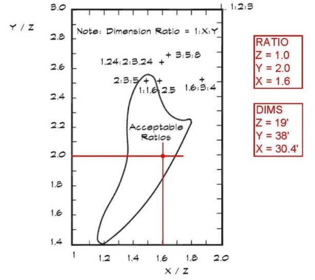
The ANSI/ASA S12.55/ISO 3745 standard offers guidelines for determining the size of hemi-anechoic rooms. Interior room dimensions are a function of test source size, radius of measurement hemisphere, and distance to the reflecting plane based on the lowest cutoff frequency. These parameters yielded a room with internal dimensions (wedge tip-to-tip) of 38’L × 38’W × 19’H at the minimum desired room cutoff frequency of 60 Hz. However, the resultant square room does not satisfy industry practice for room proportions and could be subject to undesirable standing waves. Accordingly, room dimensions were adjusted to fall within guidelines as depicted in figure 5.
HVAC Systems
HVAC system engineering for the test rooms required that special consideration be given to the scavenging of exhaust from operating engines. Marine outboards discharge engine exhaust underwater through the hub of the propeller when operating off idle. When idling, exhaust is discharged through bypass ports above the waterline. Ventilation systems are needed to safely remove exhaust gases in both modes of operation, as well as manage the heat released from a wide range of engine products.
A single-pass 100 percent outside air HVAC system is used to ventilate the test room and mitigate CO and HC emissions released during active engine testing. The system is configured with three operating modes: Setup, Test Low, and Test High. Mercury testing engineers select the operating mode based on multiple testing parameters, including engine HP and anticipated thermal cycling.
In setup mode, systems operate at their lowest flow rates, providing the minimum amount of ventilation make-up air to the continuous scavenge exhaust system while moderating the test room temperature to its design setpoint. Test Low and Test High modes are used with active engine testing, with increasingly higher ventilation rates used to manage added heat loads from increased engine HP. With the test room constructed over a water reservoir, controlling temperature and relative humidity to required tolerances proved an added challenge to a task already made difficult by the single-pass, multi-step ventilation system. Custom air handling units were configured with several heating and cooling features to allow these challenging conditions to be met.
The combination of high airflow rates and single-pass ventilation demanded specialized temperature controls given winter to summer temperature gradients characteristic of Wisconsin. With the facility’s stand-alone nature and desire for energy efficiency dictating the use of natural gas, the heating system uses three direct-fired gas burner sections arranged in a 1/3–2/3 split and equipped with 30:1 turndown control valves to allow maintenance of +/− 2°F variance from heating setpoint. This same setpoint tolerance was required when operating in cooling mode and resulted in the use of direct expansion refrigeration for cooling cycles with two condensing units sized at 1/3 and 2/3 total system capacity. Each condensing unit stages multiple compressors to match capacity with test room heat loading. Finally, fuel supply systems are interlocked with the stepped HVAC control, allowing fuel solenoids to open only when HVAC is in Test Low or Test High mode and staying closed when in Setup mode.
General building HVAC systems were selected to optimize energy efficiency and provide Mercury with a comfortable indoor environment. High-efficiency (95 percent) condensing boilers generate low-temperature hot water (100°F to 120°F based on OA reset schedule) for use in both variable volume terminal unit reheat coils as well as in-floor radiant heating. The low-temperature hot water allowed for reduced system equipment complexity and simplified control technology while eliminating the need for heat exchangers and mixing valves. Self-regulating variable speed HW heating pumps kept energy consumption low.
Office interiors utilized cloud-style suspended ceiling systems that required the careful routing of ductwork systems so it would remain hidden above the clouds yet still retain ready access to terminal unit controls for system commissioning and routine maintenance.
Fire Suppression and Safety Systems
Test rooms are equipped with low-pressure water mist fire suppression systems, the first such application of this fire suppression technology on the Mercury PD&E campus. Water mist systems are 3-D fire suppression systems that work by cooling the fire as opposed to traditional gaseous suppression systems that smother fire conditions by displacing oxygen. Water mist systems maintain safe conditions for operating personnel while minimizing damage to facility infrastructure and test equipment.
Test rooms were also equipped with Very Early Smoke Detection Apparatus (VESDA) systems used for both smoke and gas detection. VESDA systems continuously monitor the test room environment by drawing air at dozens of sampling points and scanning for smoke particulate and carbon monoxide.
Lastly, the test room fire alarm system incorporates heat detectors and infrared flame detectors to provide early warning of fire potential. These multiple safety systems are fully integrated with building, fire alarm, and ventilation systems to provide warning alarms and shutdown sequences.
Procurement and Construction
Despite a high measure of complexity owing to the acoustic and vibration isolation requirements of this facility, engineering and construction were fast-tracked to meet an aggressive occupancy target date. Engineering packages for foundations, structural steel, and building enclosure were released months ahead of architectural, mechanical, and electrical work packages. Early packages were also released for the acoustic test rooms and vibration isolation systems, ensuring these long lead specialty systems would arrive in a timely manner.
Procurement efforts were performed by both Mercury Marine and their construction manager, C. D. Smith. Long lead equipment such as acoustic test chambers were purchased months before construction began to ensure their arrival in their designated window of the project construction schedule.
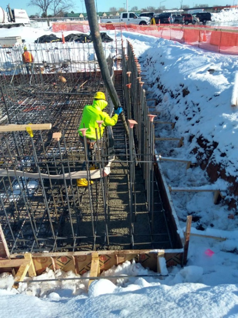
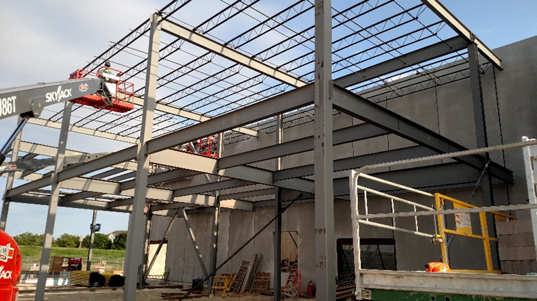
Construction began in March 2018 with the ground-breaking ceremony held on April 5, 2018. Despite inclement weather, the pouring of the two-foot-thick concrete mat foundations began just two weeks later and concluded in early May (fig. 6). The precast concrete wall panels were lifted into place in mid-May and the first structural steel building column was placed on May 29, 2018 (fig. 7). Construction continued throughout the summer with a target date for completion in November 2018.
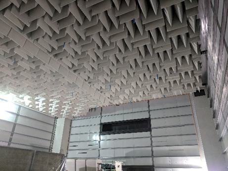
Certain construction activities were scheduled for completion earlier than typically expected to accommodate special construction tasks. Mechanical ducting and fire protection piping located above the acoustic test rooms was installed early so as to precede test room erection and allow the test installer unencumbered access to the space. The test rooms are self-supporting, and only contact the spring-isolated floor slab, maintaining the highest degree of vibration isolation possible. However, the test rooms require multiple utilities to function and, as such, there are dozens of penetrations ranging from crane supports to compressed air throughout the test room walls. Installation of these utilities required close coordination between contractors and the test room installers to ensure correct installation and location to accommodate both the test room panel structure and wedge treatment (figs. 8 and 9).
The inherent complexity of NVH facilities demands open and frequent communication between the owner, architects, engineers, and contractors. Whether it be responding to unique field conditions or debating construction sequencing, the project team was singularly focused on delivering a world-class facility to Mercury Marine.
Facility Performance
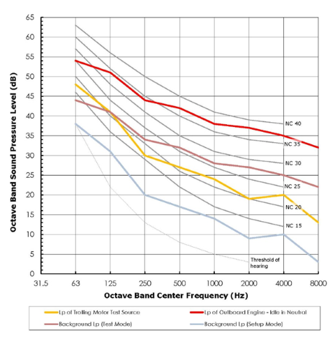
Mercury Marine provided measured sound spectra from their marine product line, including multiple examples of internal combustion engines, as well as ultra-quiet electric trolling motors. These varied spectra were used to establish a desired noise floor of approximately NC-10 (21 dBA) in the test rooms (fig. 10). During commissioning of the hemi-anechoic test chamber, background sound levels with ventilation systems off were measured at 16 dBA.
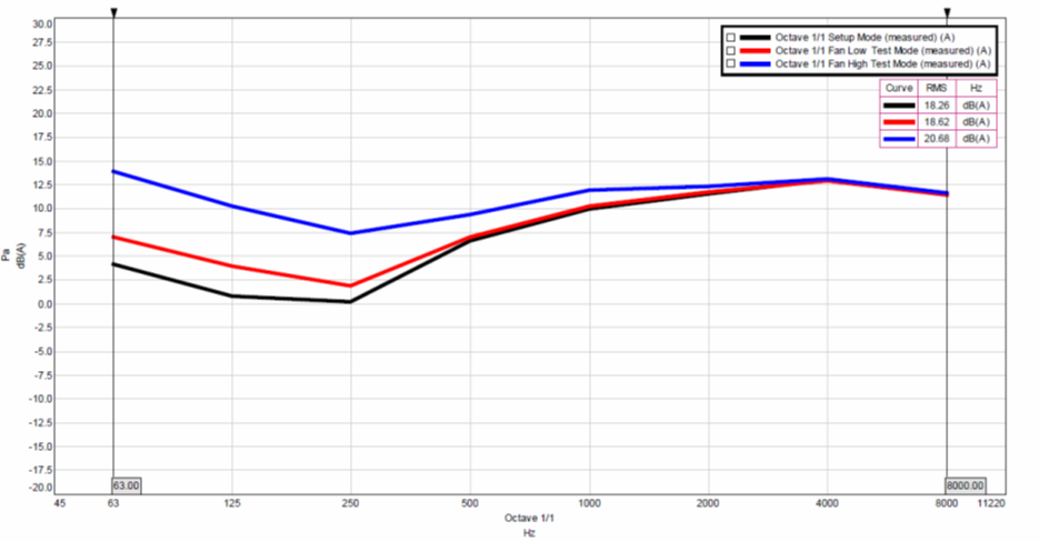
Mercury NVH engineers have since measured test chamber background sound levels at test room ventilation system operating modes of Setup, Test Low, and Test High. These three operating modes allow Mercury to select a ventilation mode to match the horsepower output of the engine under test (fig. 11).
Establishing an Industry Benchmark
Partnering efforts were of foremost importance on this project, as representatives from the engineering, construction, and supplier communities worked together to ensure its success. Mercury contracted directly with Albert Kahn for engineering services and with C. D. Smith for construction management services. They also held contracts directly with Rohde Brothers for mechanical systems engineering and construction and Pieper Electric for electrical contracting. Mercury also procured and managed direct buy contracts for major building systems, including Eckel for the acoustic test chambers, Mason Industries for vibration isolation systems, and J. F. Ahern for building fire suppression systems.
The uniqueness of this facility proved inspirational to many suppliers and constructors, who engaged in preliminary engineering and coordination efforts with enthusiasm. This proved to be significant as their experience helped the entire team to foresee problems and plan in advance for their resolution. Constructors were especially supportive in raising constructability concerns and offering alternative construction approaches essential to maintaining schedule and controlling costs. The owner’s staff were particularly engaged in the entire engineering and construction effort, clearly recognizing the importance of this investment to Mercury. Throughout the project, they offered timely decision making and expert guidance on compliance requirements relative to Mercury design and construction standards.
The Mercury Marine NVH Technical Center has established an industry benchmark for excellence in noise and vibration testing facilities. It stands as a testament to the high achievement possible with successful collaboration between the owner, architect, engineers, and contractors.
About the Author
Peter G. Lynde, PE, is senior vice president and corporate secretary with Albert Kahn Associates, Inc., Detroit, MI. He can be reached at 313-202-7880 or peter.lynde@akahn.com.
Acknowledgments
| Owner | Mercury Marine |
| David Hahn, Facilities Construction Manager | |
| Doug Czaikowski, Manager of Engineering Test Facilities | |
| Jeff Etapa, Program Director—Sea Ray | |
| Andrew Waisanen, Manager—NVH & Structures | |
| Architect-Engineer | Albert Kahn Associates, Inc. |
| Peter G. Lynde, Principal | |
| Ryan Alm, Project Architect | |
| Civil Engineering & | Excel Engineering |
| Façade Consultant | Tom Schermerhorn, Principal |
| Construction Manager | C. D. Smith |
| Jason Bos, Project Manager | |
| Kevin Halbach, Site Superintendent | |
| Mechanical Contractor | Rohde Brothers |
| Michael Rohde, President | |
| Electrical Contractor | Pieper Electric, Inc. |
| Bob Woloszyk, Branch Manager | |
| Fire Protection Contractor | J. F. Ahern Fire |
| Wade Lenz, Project Manager | |
| Acoustic Test Rooms | Eckel Industries |
| Jeffrey Morse, Vice President | |
| Acoustic Test Room Installer | Viking Enterprises, Inc. |
| David E. Engdall | |
| Vibration Isolation Systems | Mason Industries |
| Jonathan Reinhardt, Regional Sales Manager |