Vibratory Forces Acting on Supports of Machines with Rotating Elements
By Eric E. Ungar
Acentech, Inc., Cambridge, MA
The vibrations induced in a structure that supports a machine with rotating elements, such as an air handling unit that includes a fan assembly, generally are of interest in relation to controlling these vibrations and the attendant radiated noise. Here is a simple way to arrive at a reasonable estimate of the forces acting on the supporting structures, on the basis of which one can evaluate the structures’ vibrations.
Balance Grade; Force due to Unbalance
Vendors of machines with rotating elements typically indicate the so-called balance grade of the rotor assembly, which consists of the rotating element and its immediate supporting structures. The balance grade indicates the velocity amplitude measured (perpendicular to the rotor’s axis of rotation) as the assembly, mounted in a balancing machine, rotates at its rated speed.
ISO 1940-1-2003(en), Mechanical Vibration—Balance Quality,indicates balance grades in the form of “G-V,” where V denotes the velocity amplitude in millimeters per second measured on the rotor assembly in a balancing machine. (Corresponding to the balance grade G-2.5, for example, the velocity amplitude is 2.5 mm/s.)
In a balance machine, the rotor assembly is mounted on very flexible supports, as sketched in figure 1.
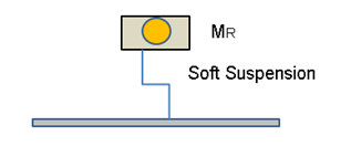
These supports may be expected to exert forces on the assembly that are negligibly small as the assembly’s displacement is very small. Thus, if one knows the mass MR of the rotor assembly (which typically is available from a machine’s vendor), one may determine the amplitude of the force FU due to the imbalance from the acceleration of the assembly corresponding to the measured velocity V as
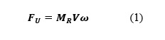
where ω denotes the rotational frequency in radians per second.
Hard Mounted Rotor Assembly
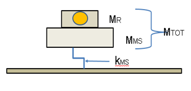
In a machine in which the rotor assembly is rigidly attached to the machine’s structure, as shown schematically in figure 2, the force FU due to the rotating imbalance acts not only on the mass of the rotor assembly but also on the mass of the rest of the machine. Since typical rotational speeds correspond to relatively low frequencies (e.g., 360 rpm = 6 Hz), it is not unreasonable to consider the rest of the machine as acting much like a rigid mass. The structures on which machines typically are mounted (e.g., concrete slabs on steel beams or trusses) tend to be relatively stiff and massive. They also may be considered as essentially rigid at the frequencies of concern.
Analysis of the classical single-degree-of-freedom system modeled in figure 2 permits one to determine the displacement amplitude of the combined masses—and from it the amplitude FSof the force acting on the supporting structure. One finds that
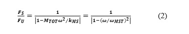
where kMS represents the stiffness of the machine’s isolation system, MTOT = MR + MMS the total participating mass, and ωMST the radian natural frequency of the total mass supported on the machine’s resilient support. With proper selection of the isolation system, this natural frequency is much smaller than the rotational frequency, so that the force FS acting on the support is only a small fraction of the imbalance force.
Internally Isolated Rotor Assembly
Consider the case where the rotor assembly is “internally isolated” from the machine structure, as shown diagrammatically in figure 3, with kIS representing the stiffness of the internal isolation and MMS the mass of the machine structure.
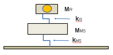
From analysis of this figure’s two-degree-of-freedom system, one finds
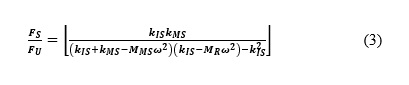
For the case where the internal spring is extremely stiff, so that the two masses essentially are joined rigidly, one finds that this equation reduces to equation (2). If, on the other hand, the stiffness kIS of the internal isolation spring is very small, as often is the case if the internal isolation is well designed, the foregoing equation reduces to
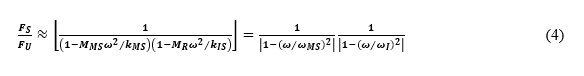
Here ωMS denotes the radian natural frequency of the machine mass connected by the machine’s isolators to a rigid support and ωI represents the natural frequency of the rotor assembly connected to a rigid support by the internal isolation. Comparison of this result with equation (2) indicates that equation (4) corresponds to two spring-mass systems in tandem.