Noise Diffraction Reduces Traffic Noise
By Ysbrand Wijnant
4Silence BV
As population increases, so does transportation. More cars, more trucks, more trains, and more airplanes are needed to transport us and all the stuff we need. Undoubtedly, this increase in traffic comes with an increase in noise pollution, and despite all our efforts to reduce it, traffic noise is still a huge problem and considered a health risk.
Classical solutions to reduce noise are more silent car and truck tires, quieter road surfaces (more open, absorbing, and smoother pavement), smoother tracks and wheels, rail dampers, and possibly more or higher noise barriers. These measures work fine and effectively to lower the emitted sound, absorb the sound, or induce reflection of sound, reducing the overall sound pressure level at the listener’s position. However, there are more ways to reduce traffic noise, and these new measures may even have additional benefits!
In lectures on acoustics given at universities all over the world, the term diffraction is taught to describe the physical phenomenon of bending sound waves around an obstacle into the “shadow region” of that obstacle. Only in the (very) high-frequency limit does an obstacle create a shadow region, and sound cannot be heard if the sound source cannot be seen. For lower frequencies (or more precisely, if the size of the obstacle is in the same order of magnitude as the wavelength of the sound), sound bends around the obstacle and can be heard by a listener behind that obstacle. This makes the obstacle less efficient in blocking noise, and it is therefore considered to be something negative for noise barriers. However, we can also use diffraction in a more positive way. If it is possible to “bend” sound waves, why not bend it into a direction where it is less annoying…like up in the air? It is exactly this feature of diffraction that is exploited by a novel type of diffractor, which is now being developed and used to diffract tire-road and railway noise.
About a decade ago, we started our journey by computer simulations. In the Structural Dynamics and Acoustics group at the University of Twente in the Netherlands, simulations were carried out to predict noise reduction of a 1 m strip of a given so-called acoustic impedance ( = the ratio between the particle velocity and the acoustic pressure). It turns out that for sound waves that propagate parallel to the surface, similar to the sound waves emitted by the tire and train wheels or rail, a minimal impedance yields a highest diffraction. The outcome of one of these simulations is shown in figures 1a and 1b. In the picture on the left, the sound pressure level of a line source that radiates at 1 kHz just above an acoustically hard ground surface, is depicted. On the right, we have introduced a 1 m wide strip of a very low impedance (Z = 0.01 ρ0 c0, where ρ0 is the mean density and c0 the speed of sound), positioned just right of the same sound source. Indeed, we observe a sharp diffraction lobe, pushing the sound in an upward direction and leaving a region of low sound pressure level behind this impedance plane.
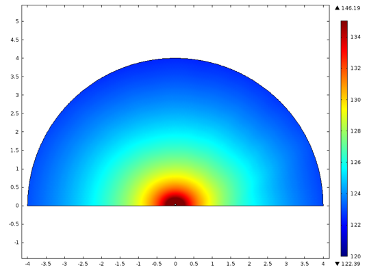
Figs. 1a and 1b. Sound pressure level for a line source at 1 kHz for a hard surface (left) and a low impedance (ξ = 0.01) strip of 1 m next to the source.
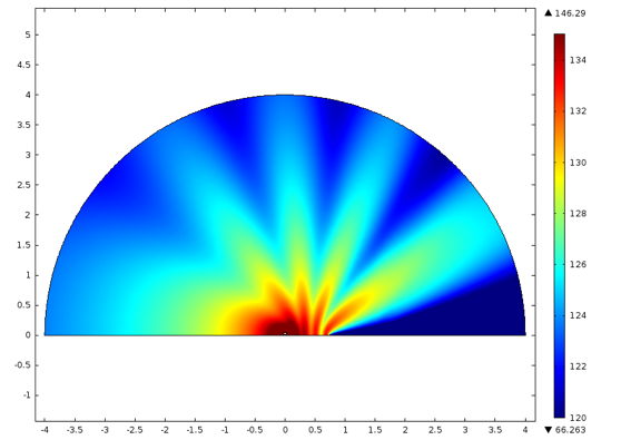
A low impedance plane can physically be created by acoustic resonators (quarter wavelength or Helmholtz resonators). The quarter wavelength resonators are pockets of air (cavities) within the ground surface, so they are very practical to accomplish. If the depth of such a cavity is approximately a quarter of the wavelength of the sound to diffract, a large diffraction is observed. This is depicted in figures 2a and 2b, where the sound pressure level is shown for the same line source as in figures 1a and 1b, but now having two cavities positioned just right of the sound source.
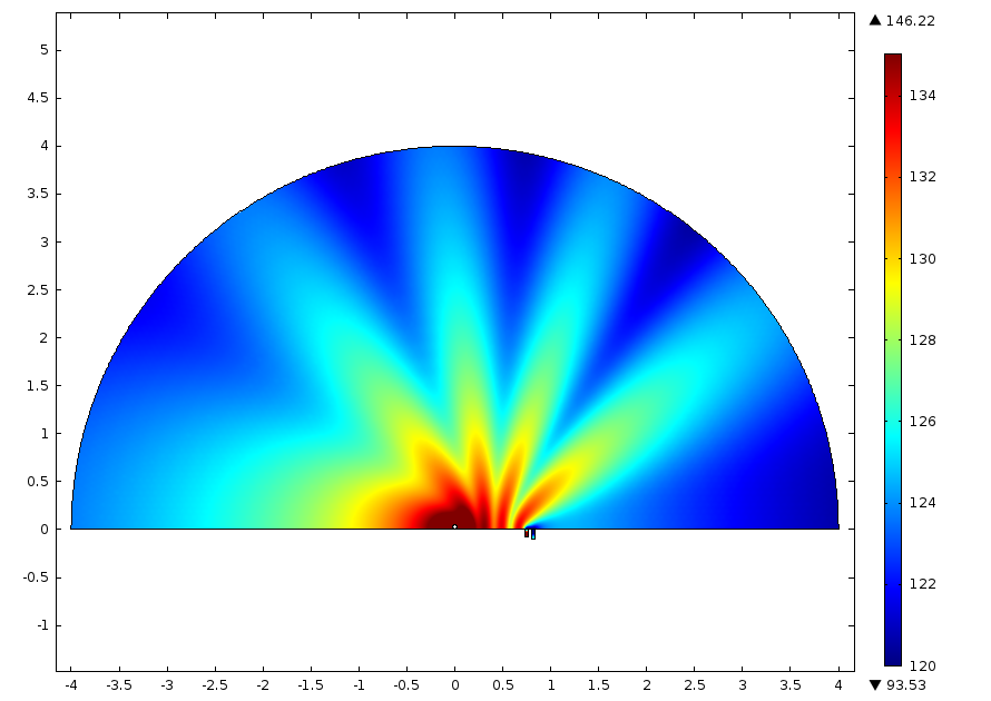
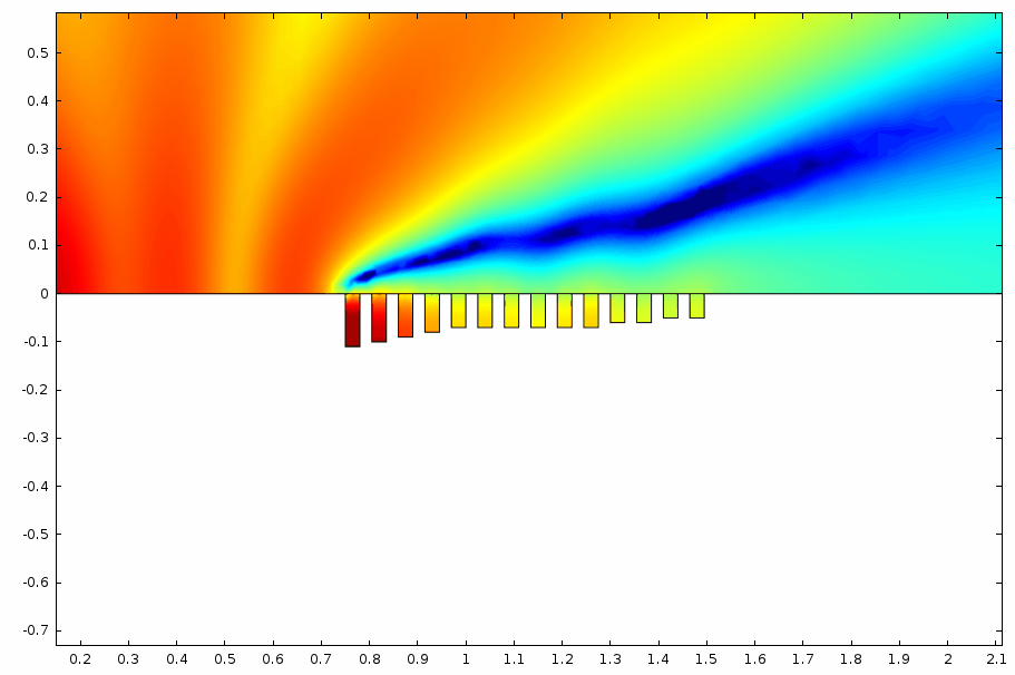
Figs. 2a and 2b. Sound pressure level for a line source at 1 kHz for a hard surface, including 2 cavities (left). Detail of a sound pressure level simulation with more resonators to reduce broadband (traffic) noise.
One drawback of the use of a single resonator is the limited frequency range at which it works. Hence, more resonators that resonate at different frequencies are needed to obtain the broadband noise reduction needed for traffic noise. A detailed study is shown in figures 2a and 2b, using more resonators tuned at the various frequencies for traffic noise.
To implement a device to diffract sound along a road surface, obviously, other issues than sound reduction are important. Safety, for instance, is such an important issue; one needs to be able to drive over the diffractor without any danger. Also, drainage is important; a water-filled pocket does not acoustically resonate, and we need to make sure that this will not be the case. All these issues have been solved over the recent years, and 4Silence, our spin-off company from the University of Twente exploiting the diffractor, has been able to develop its patented WHIS(per)stone to diffract tire-road noise. This diffractor is depicted in figure 3.
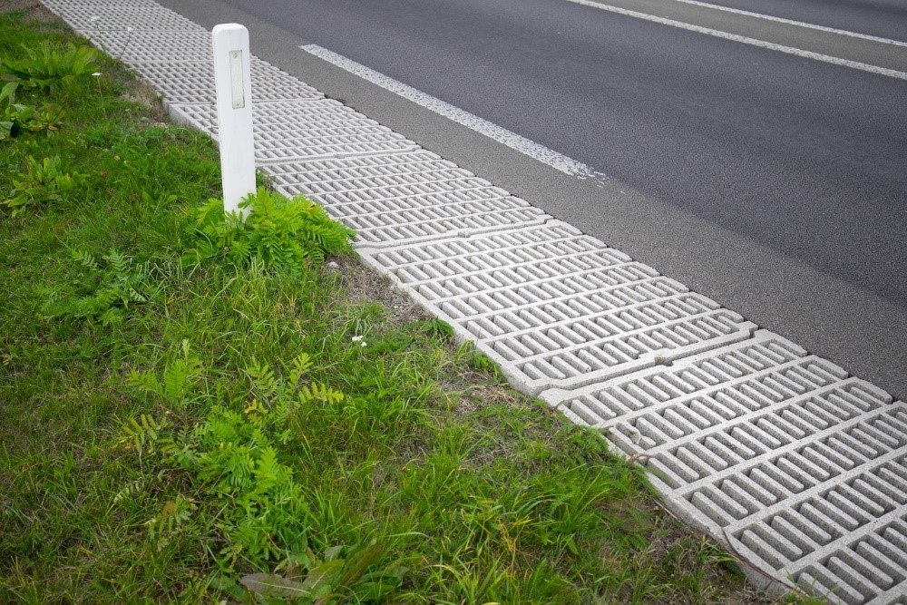
Fig. 3. 4Silence’s WHIS(per)stone.
The diffracting element is a concrete block where resonating pockets of various depths induce diffraction. An induced reduction of 2–3 dB has been measured for road traffic noise. This is shown in figure 4, where a typical acoustic measurement is shown of a pass-by experiment—a car drives along a diffractor and a reference section where no diffractor is placed, and the difference between the sound pressure levels is recorded. Figure 4 shows the sound pressure level as a function of time of two microphone arrays, where both arrays are placed at 7.5 m away from the road and each array contains four microphones at, respectively, 1.2, 2, 3, and 4 meters of the ground (the measurements for these different microphones are indicated in figure 4 by the numbers 1, 2, 3, and 4). One array (indicated by D) is positioned behind the diffractor, and one array (indicated by R) is positioned behind a reference cross section where no diffractor is placed. The measurement clearly shows the passing of the vehicle (one sees an increase and subsequent decrease in sound pressure level). The difference in sound pressure level between the low-height microphones and high-height microphones is clearly seen in the diffraction section, whether or not it is seen in the reference cross section.
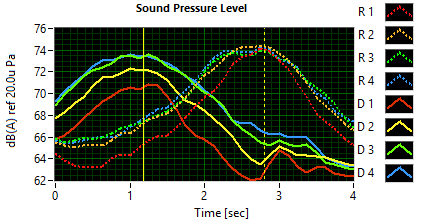
Fig. 4. A typical pass-by measurement of two microphone arrays at 7.5 m from the road; one behind a diffractor (D) and one behind a reference cross section without a diffractor (R). The number indicates the approximate height of the microphone.
To further increase the diffracting performance, a double row of diffracting elements can be used, as shown in figure 5.
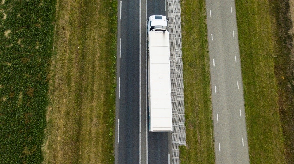
Fig. 5. A double row of WHISstones doubles the diffraction.
An obvious advantage of a diffractor positioned in the ground is that it does not block the view, and the concrete blocks are actually safer than a grassy roadside (especially for motorcyclists, for whom there is hardly any traction on grass). A possible drawback is, of course, the limited reduction for such a line of sight sound barrier (the sound source can still be seen by the listener).
To increase a noise barrier’s performance, one can use a diffractor on top of the noise screen. This is why 4Silence developed a WHIS(per)wall and WHIS(per)top, as are shown in figures 6a, 6b, and 7. The WHISwall is a Corten steel diffracting element on top of a low height (only 76 cm) noise barrier, and the WHIStop is an aluminum lightweight diffractor that can be placed on top of an existing noise barrier of any height. As one does not need to be able to drive over the diffractor, we are able to further increase the acoustic performance and induce more diffraction over a wider frequency range. In addition, the noise barrier increases the reduction behind the screen as more sounds are being reflected or absorbed. Figures 6a and 6b show the WHISwall positioned alongside a railway track. One clearly sees the quarter-wave pockets, and because of the varying depths, they reduce sound over a wide frequency range.
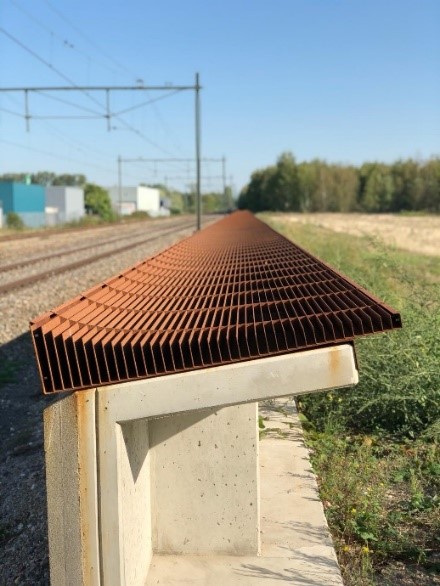
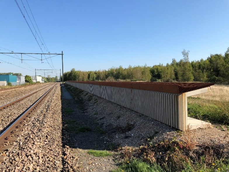
Figs. 6a and 6b. The WHISwall including noise absorbing material.
The measured overall reductions for railway noise, at 15 m distance from the center of the track and at 2 m height, are shown in figure 7; about 6.5 dB for trains that run closest to the WHISwall and about 4 dB for trains running at a larger distance (12 m from the closest track) on the opposite track.
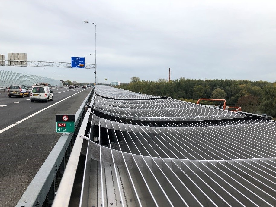
Fig. 7. The WHIS(per)top.
Thus, besides silent road surfaces and noise barriers, a new way of noise reduction is available—noise diffraction. If it is within the ground surface or on top of low-height noise barriers, this new way to reduce noise has the great advantage of not blocking the view and therefore allows for a more elegant, efficient, and cost-effective way to reduce traffic noise.
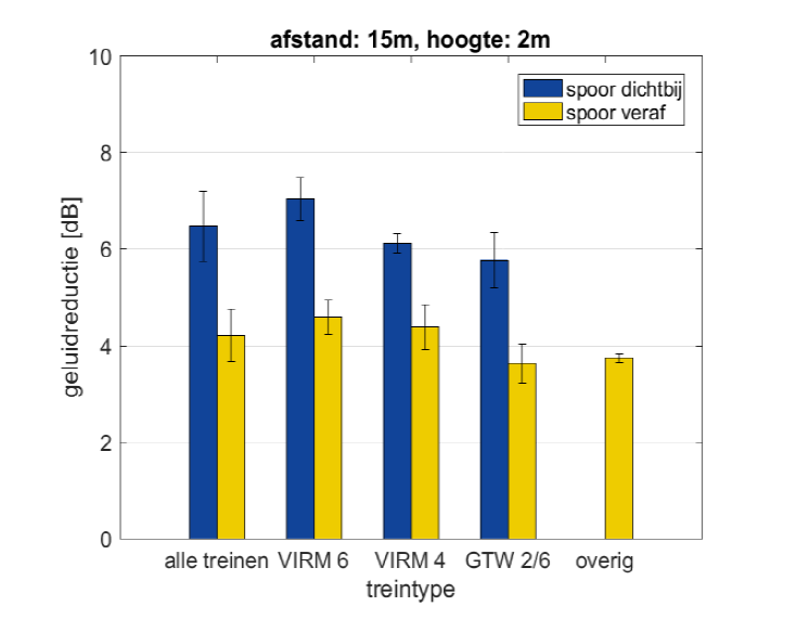
Fig. 8. The reduction of a WHISwall for railway noise.
Interested to know more? Please contact the author at y.h.wijnant@4silence.nl, or follow 4Silence on www.4silence.com/ or LinkedIn.